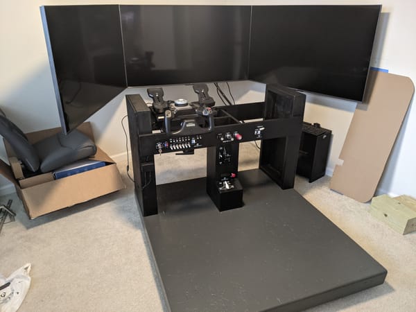
Cockpit Platform

PLANNING
Requirements
- Support the full cockpit frame and seated pilot
- Allow repositioning within the room
- Maintain a fixed, repeatable mounting interface for future airframes
- Keep overall height compatible with a C172 seating geometry
Constraints
- Must fit through a standard interior doorway when fully assembled
- No permanent attachment to the room or floor
- Built using readily available materials and basic shop tools
COMPONENTS
Materials
- 2×6 construction lumber (kiln-dried)
- (1) sheet - 7/16" OSB
- Exterior-grade wood screws
- Wood filler
- Primer and floor-grade paint
Hardware
- (4) rolling caster wheels
- Threaded inserts / T-nuts
- Grade 8 bolts and washers (cockpit attachment points)
Tools
- Miter saw
- Drill / impact driver
- Countersink bit
- Clamps
- Square and tape measure
BUILD PROCESS
Frame
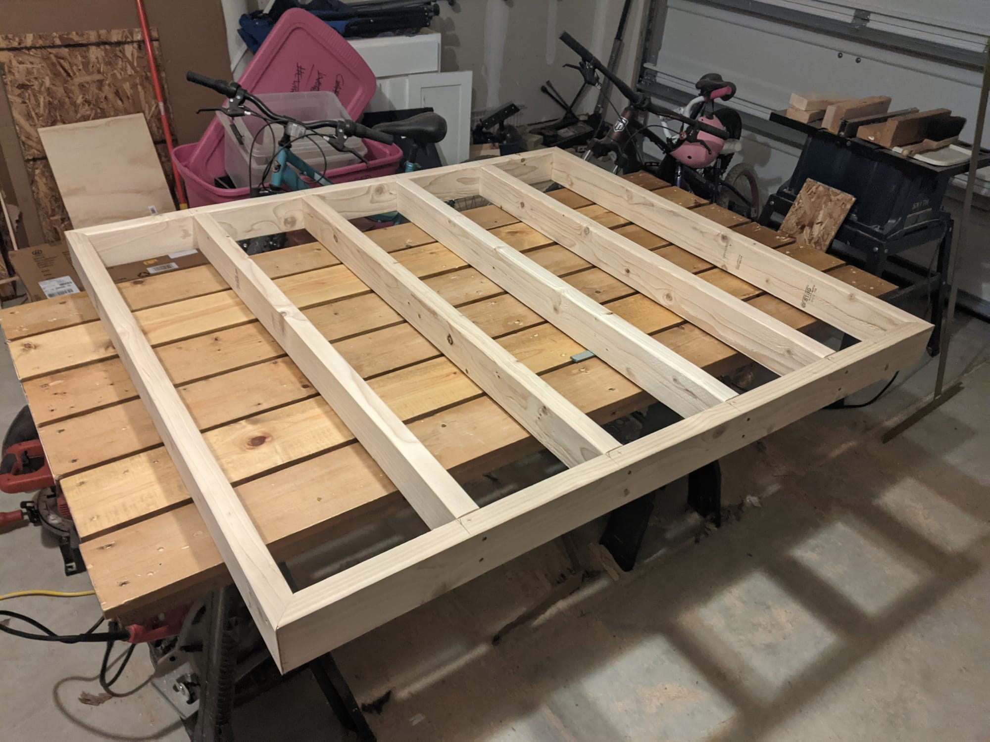
The frame was constructed from 2×6 lumber with cross members spaced to support the plywood deck without deflection. All joints were glued and screwed, then checked for square before proceeding.
Deck
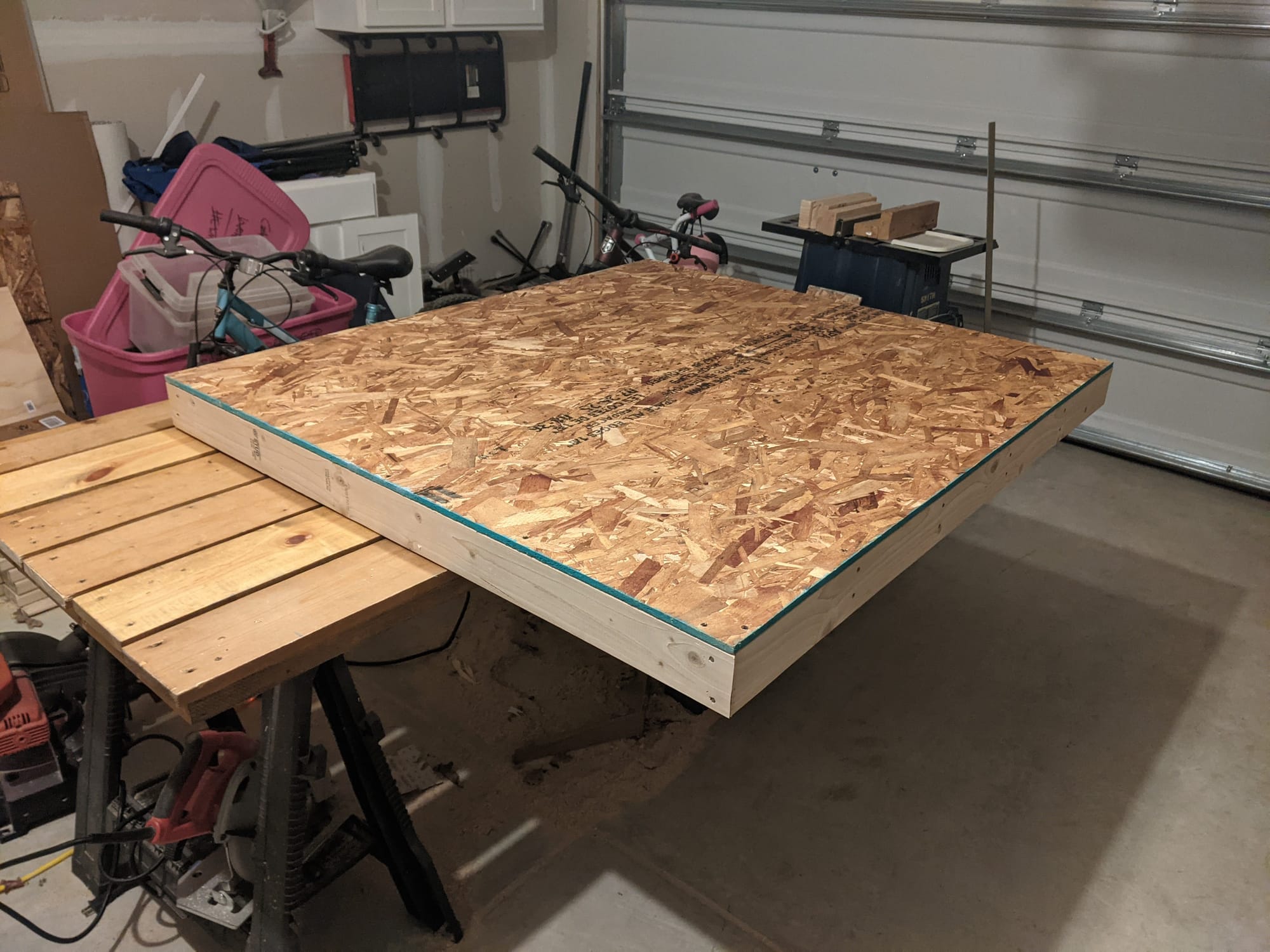
A single sheet of 3/4" plywood was cut to size and fastened to the frame. All fasteners were countersunk to allow for a smooth, uninterrupted surface for the cockpit frame.
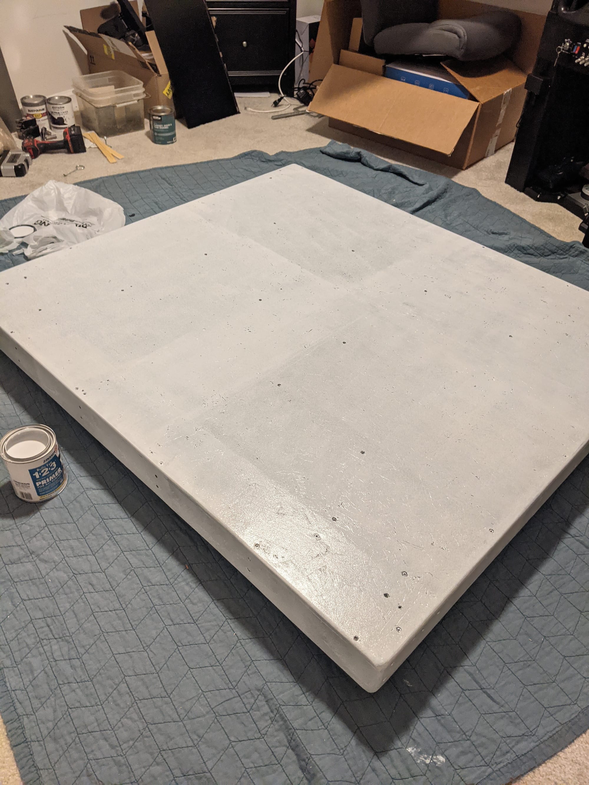
Surface Prep
Surface prep copy.
Prime
Prime copy.
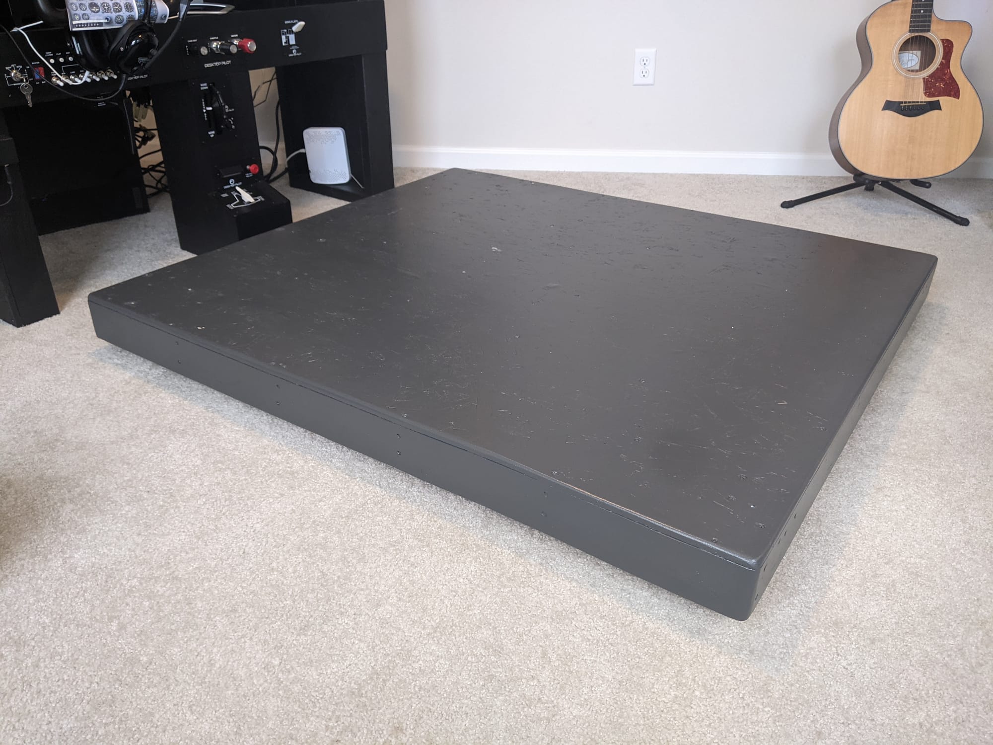
Paint
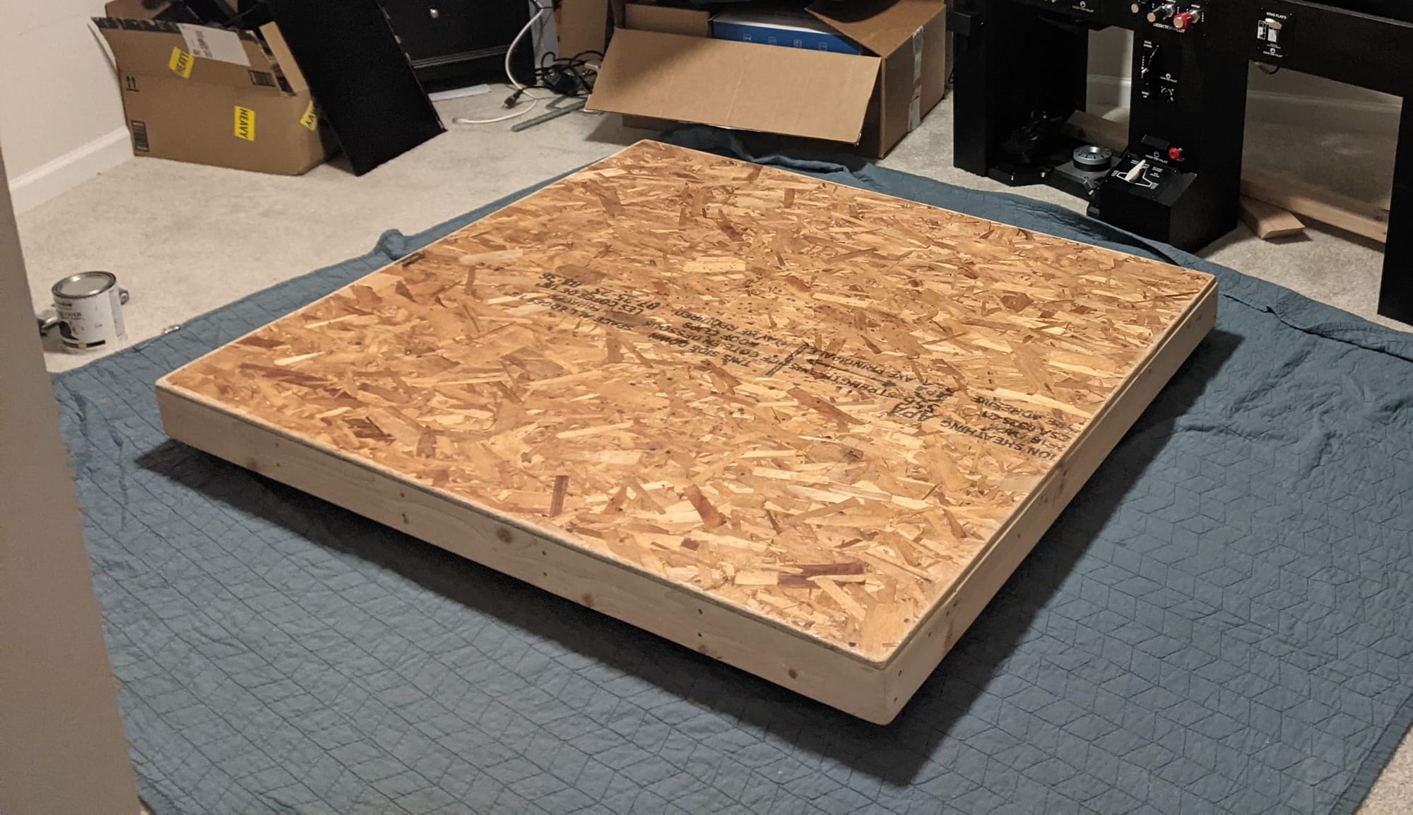
All exposed wood surfaces were filled, sanded, primed, and painted. This step was done after drilling all holes to avoid damaging finished surfaces later.
The paint provides basic protection and makes future modifications easier to spot and clean.
Caster Wheels
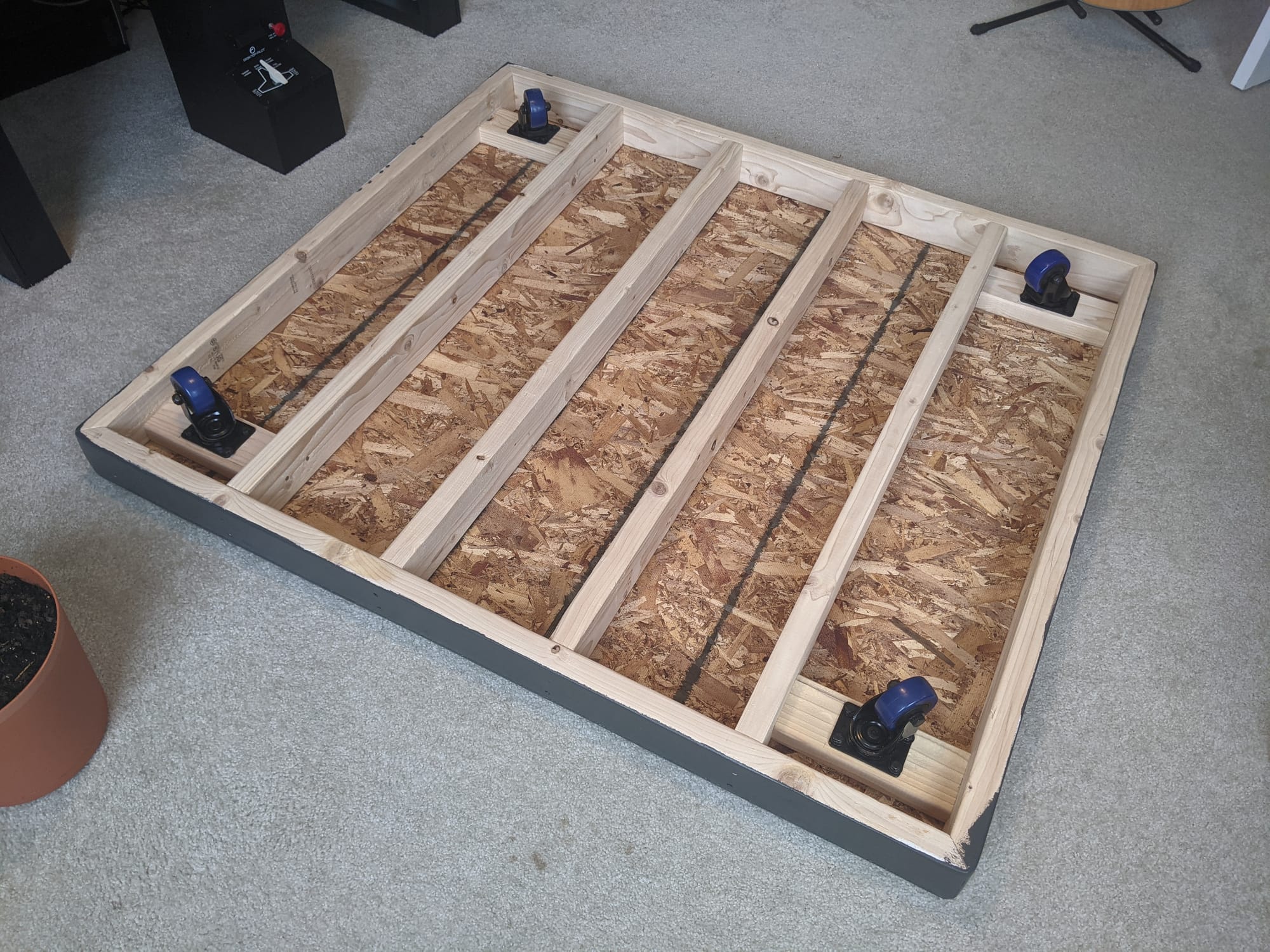
Four locking casters were mounted near the corners, positioned to distribute weight evenly while maintaining clearance for bolts and future anchor points.
Caster placement was finalized before drilling to avoid interference with cockpit mounting hardware.
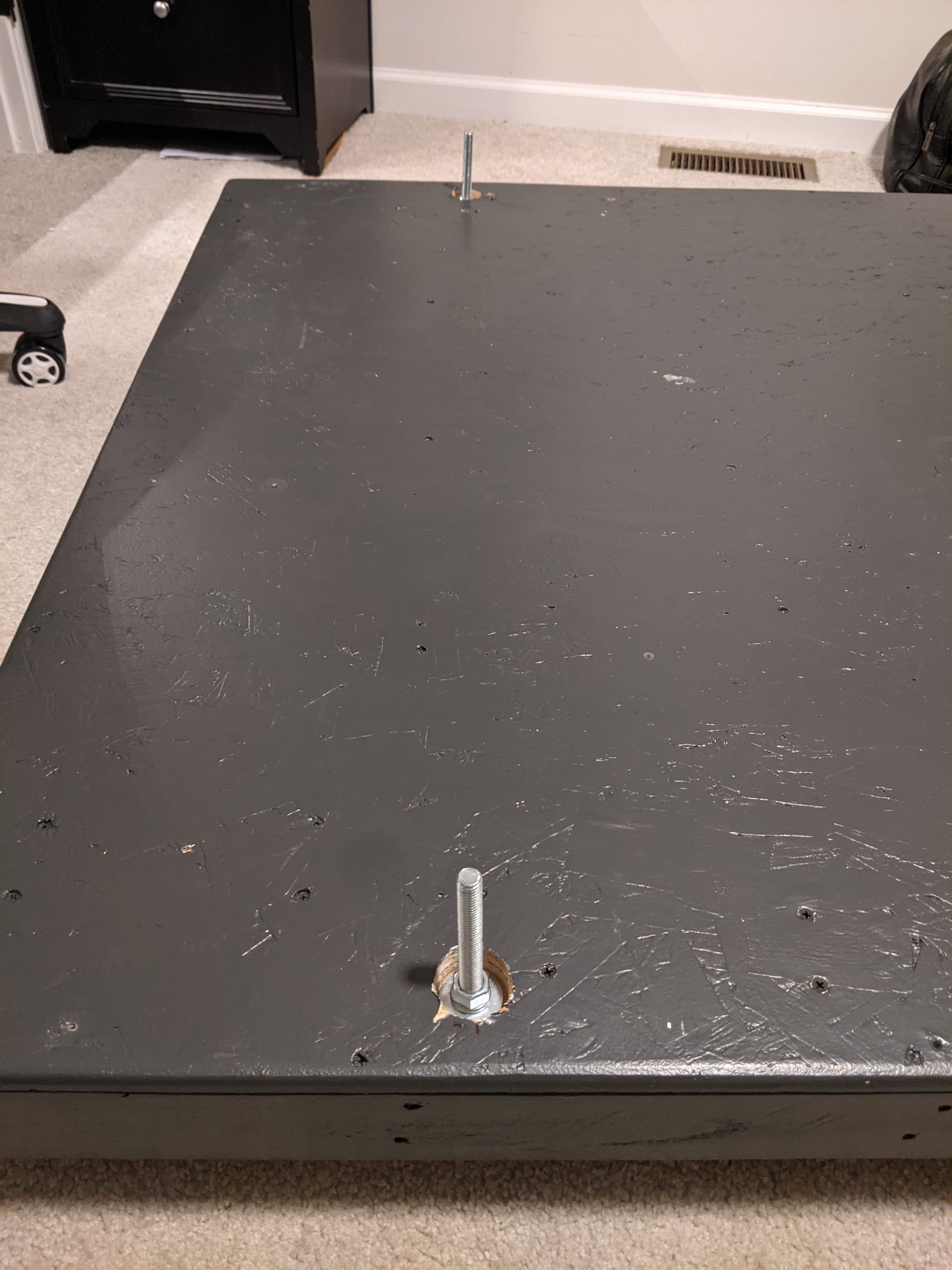
Console Anchors
Threaded anchors were permanently installed through the deck and frame. These define the cockpit attachment interface and allow the cockpit frame to be bolted down or removed without accessing the underside of the platform.
Anchor spacing was based on the cockpit frame design, not aesthetic alignment.
REVIEW
- Initial caster placement conflicted with planned anchor locations and required repositioning before drilling.
- One frame member required replacement due to warping discovered during dry fit.
BUILD PHOTOS