Flight SIM Platform
PLANNING
planning | components | build steps
Requirements
- can be easily re-positioned
- supports the full weight of the completed cockpit and pilot
- size accommodates actual size of all control and seating structures
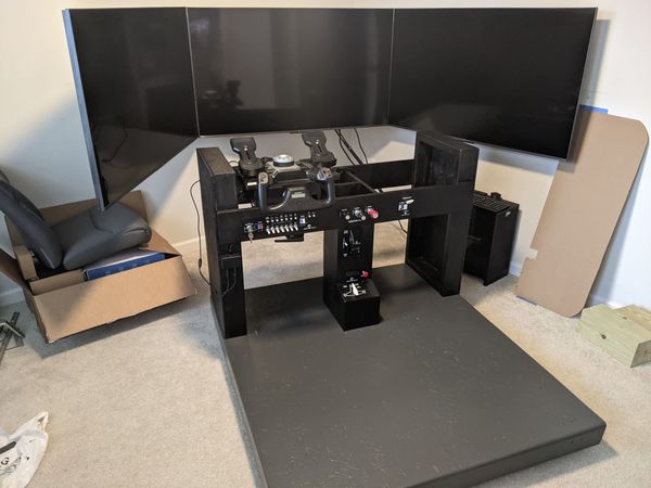
- permits secure attachment of various, interchangeable, cockpit versions
Constraints
- total height not to exceed width of standard sized interior doorway
- not fixed to floor or wall
COMPONENTS
planning | components | build steps
Materials
- 6 - 2x4 studs
- 1 - 7/16" OSB
- paint primer
- cabinet grade paint
Hardware
Casters
- 4 - rolling caster wheels
- 16 - black lag screws
- 16 - black washers
Lower Panel Anchors
- 2 - bolts
- 4 - washers
- 2 - lock washers
- 2 - wing nuts
Tools
Platform Frame
- skill saw or miter saw
- tape measure
- framing nailer
- nails
Decking / Paint Prep
- skill saw or table saw
- t-square or chalk box
- drill / impact driver
- drywall screws
- belt sander or sand paper and wood block
Paint
- rag
- paint can opener
- mini paint roller
Lower Panel Anchors
- tape measure
- speed square
- spade bit
- drill bit
- drill / impact driver
- open socket wrench
- socket
BUILD STEPS
planning | components | build steps
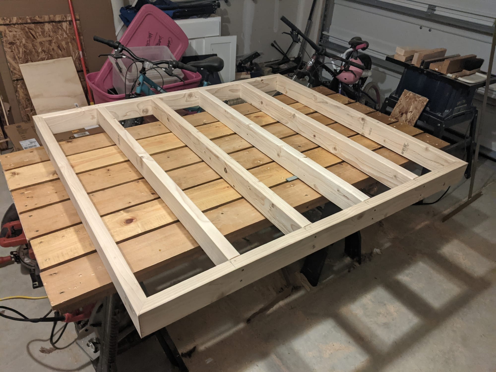
1. Frame Platform

- cut (2) 2 x 4s to 48" with ends mitered
- cut (2) 2x4s to 54" with ends mitered
- cut (4) 2x4s to 45"
- Nail together using
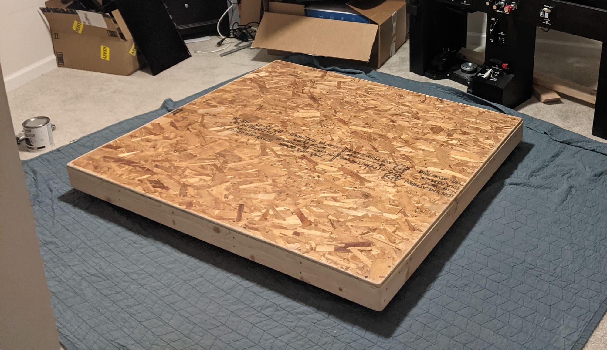
2. Secure OSB Decking
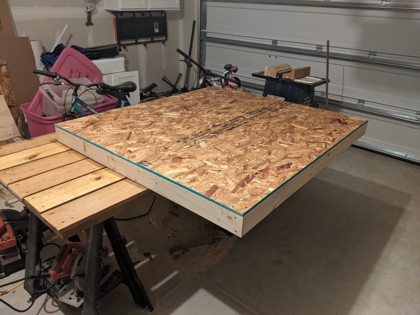
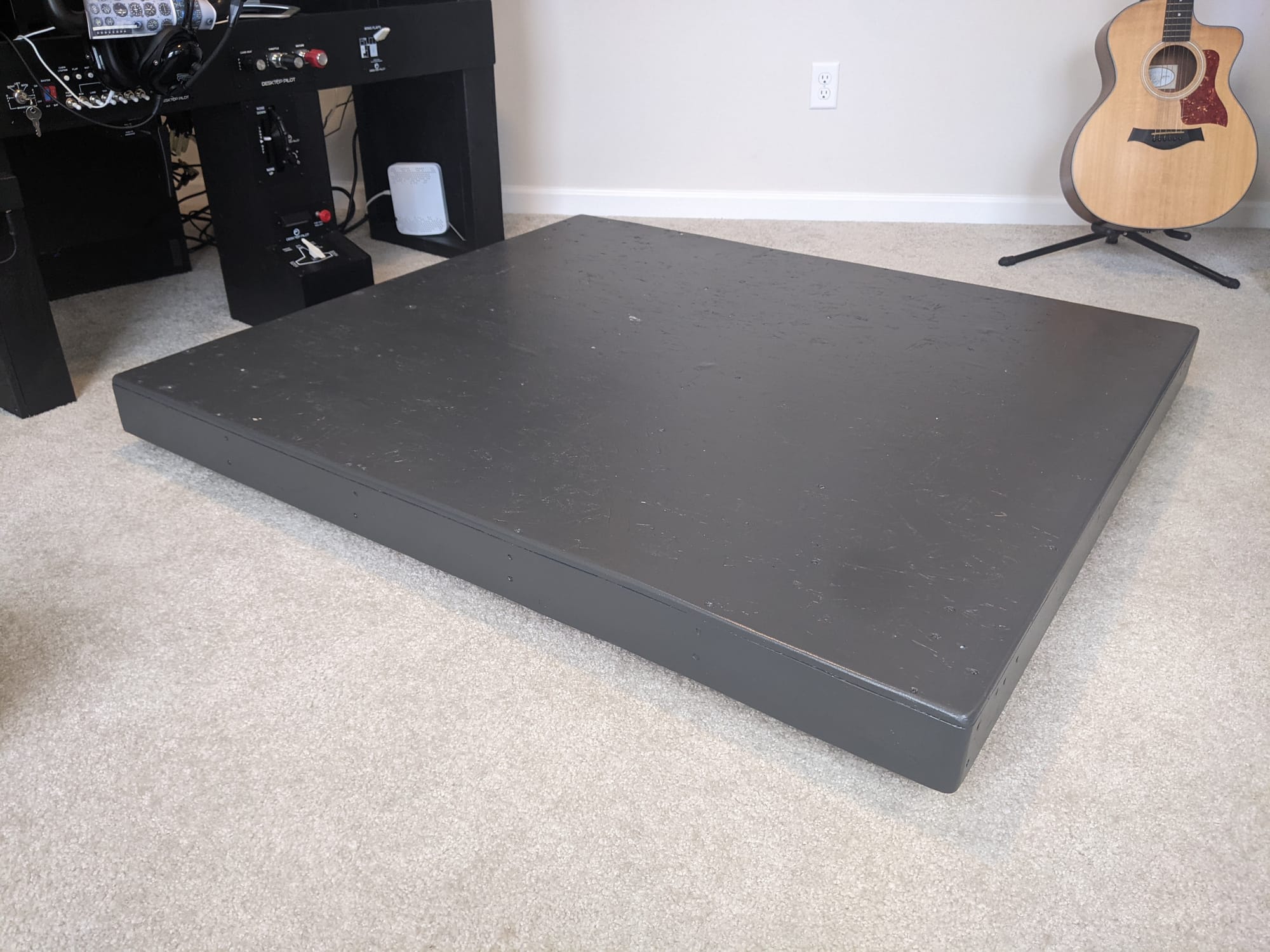
A single sheet of 3/4" plywood was cut to size and fastened to the frame. All fasteners were countersunk to allow for a smooth, uninterrupted surface for the cockpit frame.
3. Prepare Surface for Paint
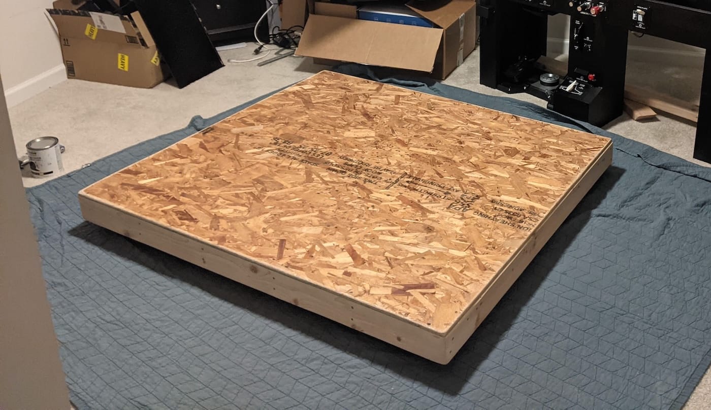
Surface prep copy.
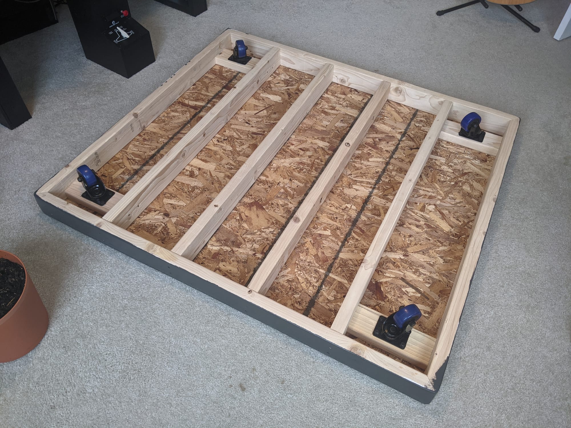
4. Attach Caster Wheels

- cut 4 2x4s to 9"
- nail blocks perpendicular in joist bays
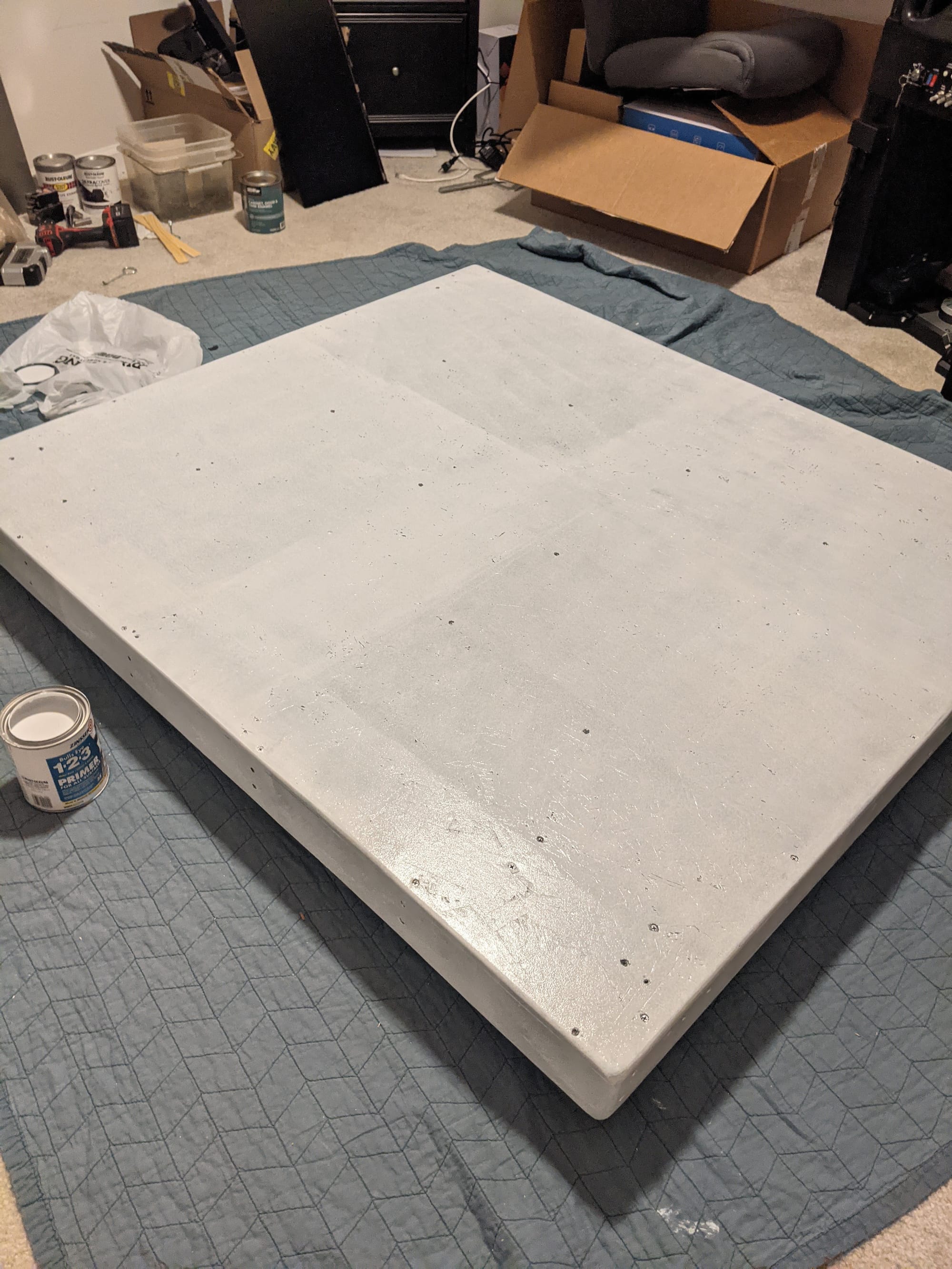
5. Apply Paint Primer
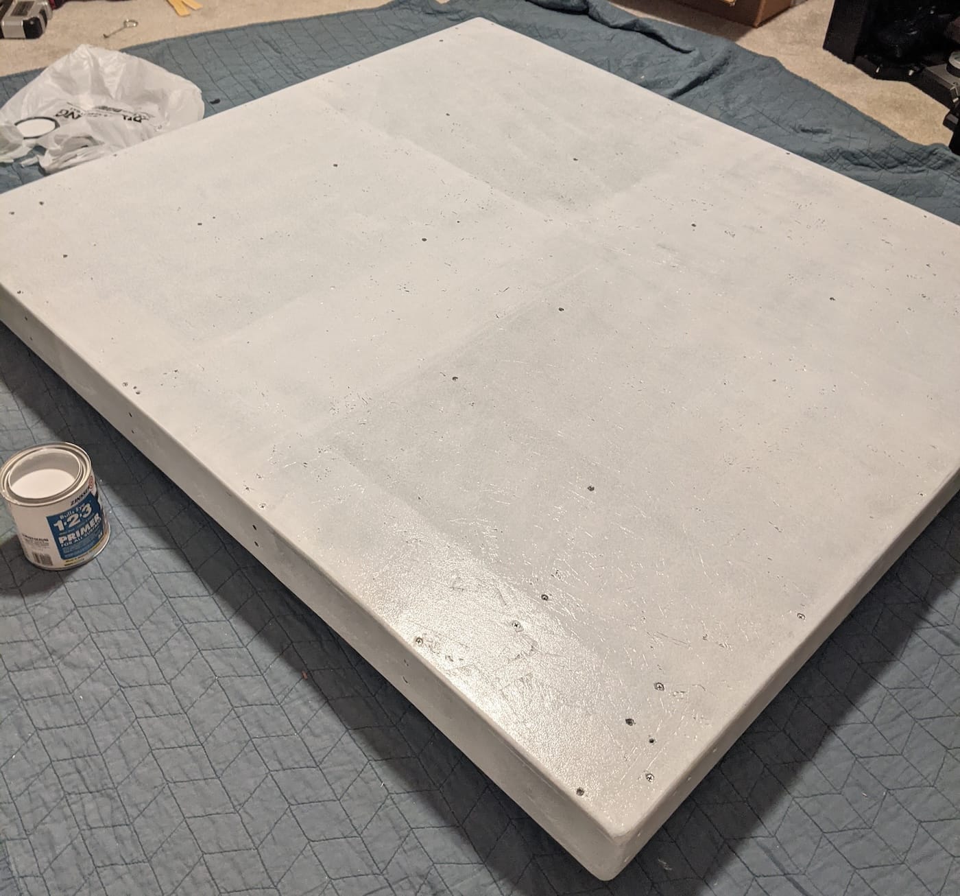
Prime copy.
6. Paint Platform

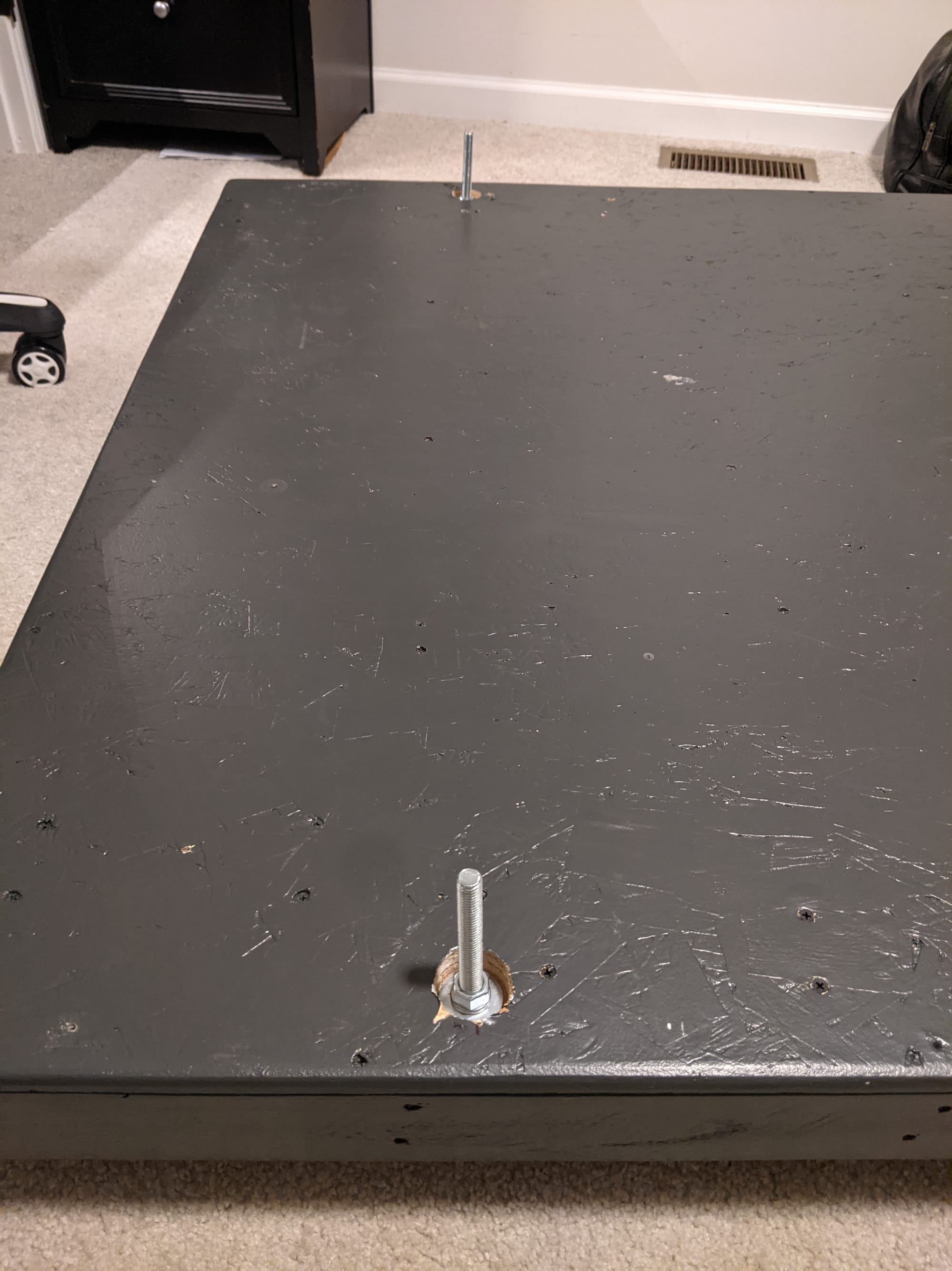
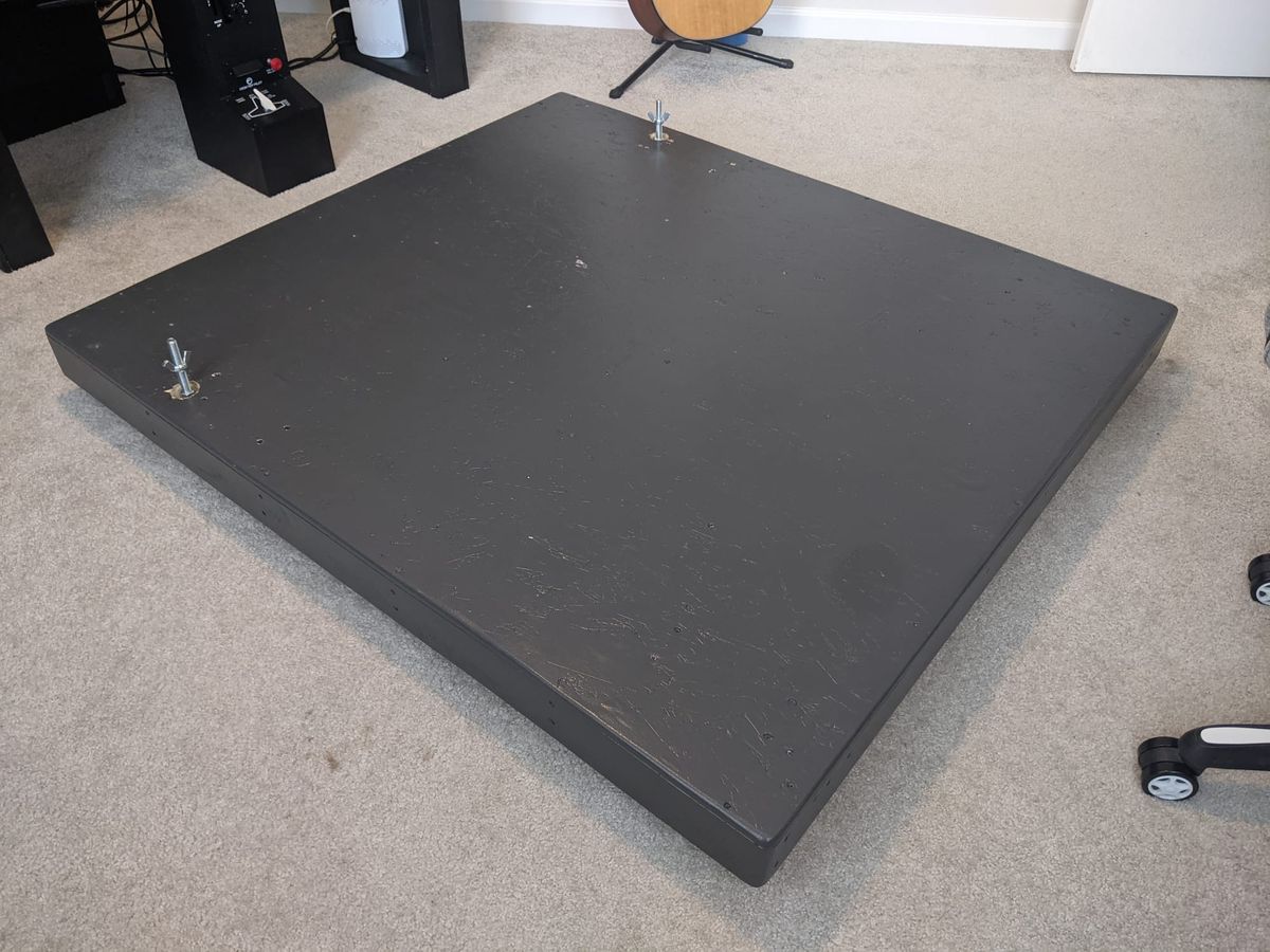
7. Install Console Anchors

Threaded anchors were permanently installed through the deck and frame. These define the cockpit attachment interface and allow the cockpit frame to be bolted down or removed without accessing the underside of the platform.
Anchor spacing was based on the cockpit frame design, not aesthetic alignment.
REVIEW
- Initial caster placement conflicted with planned anchor locations and required repositioning before drilling.
- One frame member required replacement due to warping discovered during dry fit.
BUILD PHOTOS